Statues
Description/Usage
8hp
Not trying to get all MI-y with the name, it comes from the children's game also known as Red Light Green Light.
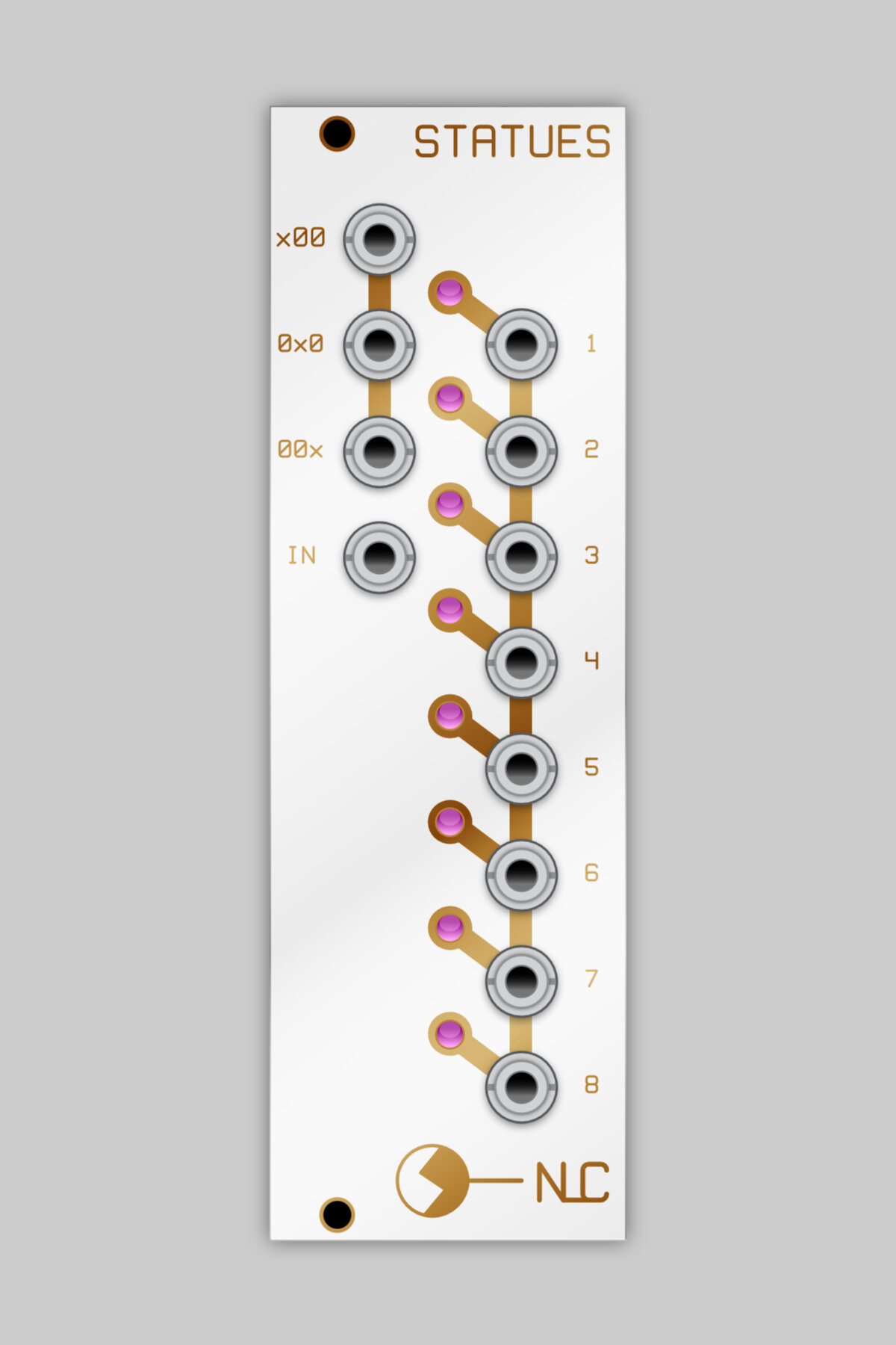
This is a 1 to 8 multiplexor….or multiplexer if you prefer….with a thru and hold circuit attached to each output. the active output is chosen by whichever combination of the x00, 0x0 & 00x inputs is high. You can put any signal into these, crossing 1V will send it high. In the demo video, I used the /2, /4 & /8 outputs from a Divide & Conquer which gives it a regular 1-8 count. Using any old signals will give a more random effect but patterns will still emerge.
IN is the signal getting processed. This module can be used to process CV and/or audio signals.
Inputs
xOO: first bit of a 0-7 number
OxO: second bit of a 0-7 number
OOX: third bit of a 0-7 number
IN: cv/audio signal
If xOO = 1, OxO = 0 and OOx = 1, you have the binary number 101. Converted in decimal : 5, so the output 6 is selected (you have 1 to 8 channels).
Outputs
The output selected by the x00, 0x0 and 00x inputs is fed the input signal (thru). When the selected output is changed the signal is held at whatever voltage it happens to be (ranges from approx -11V to 11V) (hold)
DIY
Description/Usage
8hp
Not trying to get all MI-y with the name, it comes from the children's game also known as Red Light Green Light.
This is a 1 to 8 multiplexor….or multiplexer if you prefer….with a thru and hold circuit attached to each output. the active output is chosen by whichever combination of the x00, 0x0 & 00x inputs is high. You can put any signal into these, crossing 1V will send it high. In the demo video, I used the /2, /4 & /8 outputs from a Divide & Conquer which gives it a regular 1-8 count. Using any old signals will give a more random effect but patterns will still emerge.
IN is the signal getting processed. This module can be used to process CV and/or audio signals.
Inputs
xOO: first bit of a 0-7 number
OxO: second bit of a 0-7 number
OOX: third bit of a 0-7 number
IN: cv/audio signal
If xOO = 1, OxO = 0 and OOx = 1, you have the binary number 101. Converted in decimal : 5, so the output 6 is selected (you have 1 to 8 channels).
Outputs
The output selected by the x00, 0x0 and 00x inputs is fed the input signal (thru). When the selected output is changed the signal is held at whatever voltage it happens to be (ranges from approx -11V to 11V) (hold)


