PSEUDO
Description/Usage
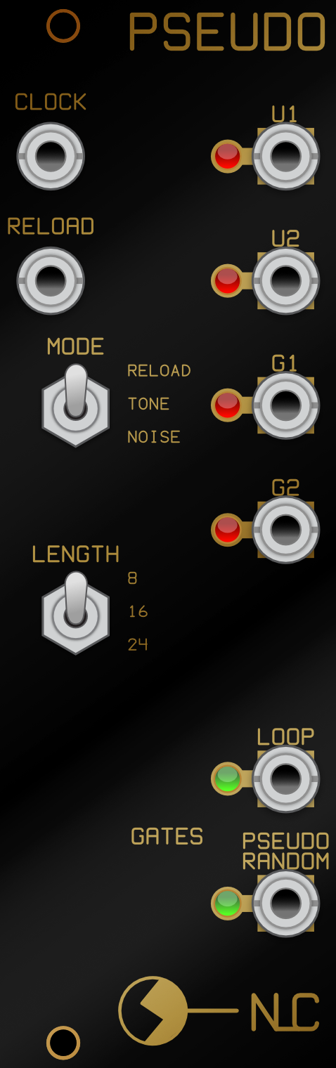
8hp
Pseudo is a pseudo-random binary sequence/noise/tone generator based on ideas presented in Electronotes #76.
It can be used in 2 ways:
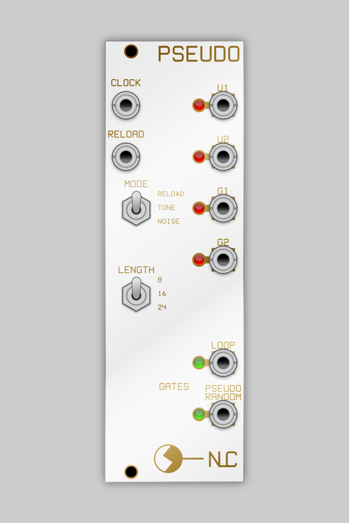
1. Pattern generator supplying 4 different CV signals and 2 gates. It can be locked into loops of 8, 16 or 24 steps, which can be reset by the switches or a gate signal.
2. Noise/tone source - a fast clock signal from a VCO allows the module to generate harmonically rich tones, again in 8, 16 or 24 steps, and pseudo random noise
It has a number of differences to the EN76 circuit, notably CMOS chips rather than TTL, it requires an external clock to run and drops the probability switches, instead there is an external input for resetting the capture wheel, or just do it manually with the switch.
The circuit contains two 24 stage shift registers. One is moved around by the incoming clock and has a modulo-2 feedback sub-circuit; this allows for a sequence of over 16.7 million steps, with an 18 kHz clock it would take about 15 minutes to repeat itself.
The second shift register section can be set to loop or repeat itself after 8, 16 or 24 stages and the loops can be refreshed by a gate/trigger or simply toggling the switch. It can also be set to not loop or repeat itself (noise).
The CV outputs are set up differently to each other.
U1 and U2 are binary weighted, similar to digital to analogue circuit (DAC). U1 takes its 6 inputs from a spread across the 24 stages. U2 gets them from 6 consecutive stages.
G1 and G2 enjoy a Gaussian distribution, more like a bell curve. Similarly G1 gets its 6 inputs from a spread across the 24 stages, G2’s are consecutive.
G1 and G2 outputs are more predictable and can often look like a slightly glitchy sine wave but some resets will give you some very odd patterns. U1 and U2 outputs are usually all over the place. These outputs generally range between +/-5V tho sometimes can stray outside of this range or be less than +/-5V.
The gate outputs range from 0-5V. Loop will give 8, 16 or 24 step gate patterns that reset along with the CVs. Pseudo Random is the one output not connected to the Loop section; it continuously supplies a pseudo random series of gates that are useful as fake white noise at fast clock rates..
DIY
Description/Usage
8hp
Pseudo is a pseudo-random binary sequence/noise/tone generator based on ideas presented in Electronotes #76.
It can be used in 2 ways:
1. Pattern generator supplying 4 different CV signals and 2 gates. It can be locked into loops of 8, 16 or 24 steps, which can be reset by the switches or a gate signal.
2. Noise/tone source - a fast clock signal from a VCO allows the module to generate harmonically rich tones, again in 8, 16 or 24 steps, and pseudo random noise
It has a number of differences to the EN76 circuit, notably CMOS chips rather than TTL, it requires an external clock to run and drops the probability switches, instead there is an external input for resetting the capture wheel, or just do it manually with the switch.
The circuit contains two 24 stage shift registers. One is moved around by the incoming clock and has a modulo-2 feedback sub-circuit; this allows for a sequence of over 16.7 million steps, with an 18 kHz clock it would take about 15 minutes to repeat itself.
The second shift register section can be set to loop or repeat itself after 8, 16 or 24 stages and the loops can be refreshed by a gate/trigger or simply toggling the switch. It can also be set to not loop or repeat itself (noise).
The CV outputs are set up differently to each other.
U1 and U2 are binary weighted, similar to digital to analogue circuit (DAC). U1 takes its 6 inputs from a spread across the 24 stages. U2 gets them from 6 consecutive stages.
G1 and G2 enjoy a Gaussian distribution, more like a bell curve. Similarly G1 gets its 6 inputs from a spread across the 24 stages, G2’s are consecutive.
G1 and G2 outputs are more predictable and can often look like a slightly glitchy sine wave but some resets will give you some very odd patterns. U1 and U2 outputs are usually all over the place. These outputs generally range between +/-5V tho sometimes can stray outside of this range or be less than +/-5V.
The gate outputs range from 0-5V. Loop will give 8, 16 or 24 step gate patterns that reset along with the CVs. Pseudo Random is the one output not connected to the Loop section; it continuously supplies a pseudo random series of gates that are useful as fake white noise at fast clock rates..